Fingers 7.7-7.9

Hey all,

The next two mechanical updates will come in relatively quick succession because a lot has happened in the past two weeks and I haven’t made the time to write about them until now. This installment will just talk about the tweaks in the finger design and what needs to be done to finish it up.

V7.6 printed fairly poorly and didn’t have great grip. The V7.7 and on has a flexible polyurethane “skin” built out simple arches. These arches seem to work well for a few reasons:

  • As elliptical arches, they print pretty well (very little overhang).
  • As elliptical arches, they are also pretty weak when pushed from the side. This comes in handy as the finger curls and has to push some of the “skin” out of the way to fully flex. This compliant aspect of the arches will hopefully enable the hand to pick up small or irregular shapes
  • The overlapping arches make a bumpy palmar surface, which aught to get better grip on odd shapes. Along with the natural tendency for polyurethane to have a high coefficient of friction with other materials (there must be a word for that), the fingers should be able to grip a wide range of objects without as much force as other, rigid-body fingers.

Another “advancement” in more recent iterations has to do with the build setup: as suggested by Alex Crease and Shane Kelly, some of the 3D printing experts at Olin, I added blue tape to the heated build plate of the Replicator 2X. This really helps build adhesion, but not quite enough to consistently prevent warping. As such, I also added a raft in the printer settings, and that holds down the fingers pretty well.

IMAG00091

The raft-cutting process gets a bit messy

Unfortunately, this raft also necessitates the new step of cutting off said raft. ABS rafts stick particularly well to their models, so I’ve had to go down the dorsal side of each finger and cut off the raft with a knife. When you get the hang of it, it goes pretty quickly, but it would be ideal if future printers could fix ABS’s peeling problem without a raft.

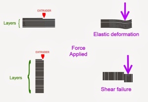
The next and most recent improvement was the addition of the 90 degree metacarpophalangeal (knuckle) joint. This long-overdue addition finally allowed the fingers to face the Instron tensile test in our materials science lab. This tensile test was done to establish how much force the polyurethane bushings could hold before shearing. The results were quite surprising:

7-8Tensile1

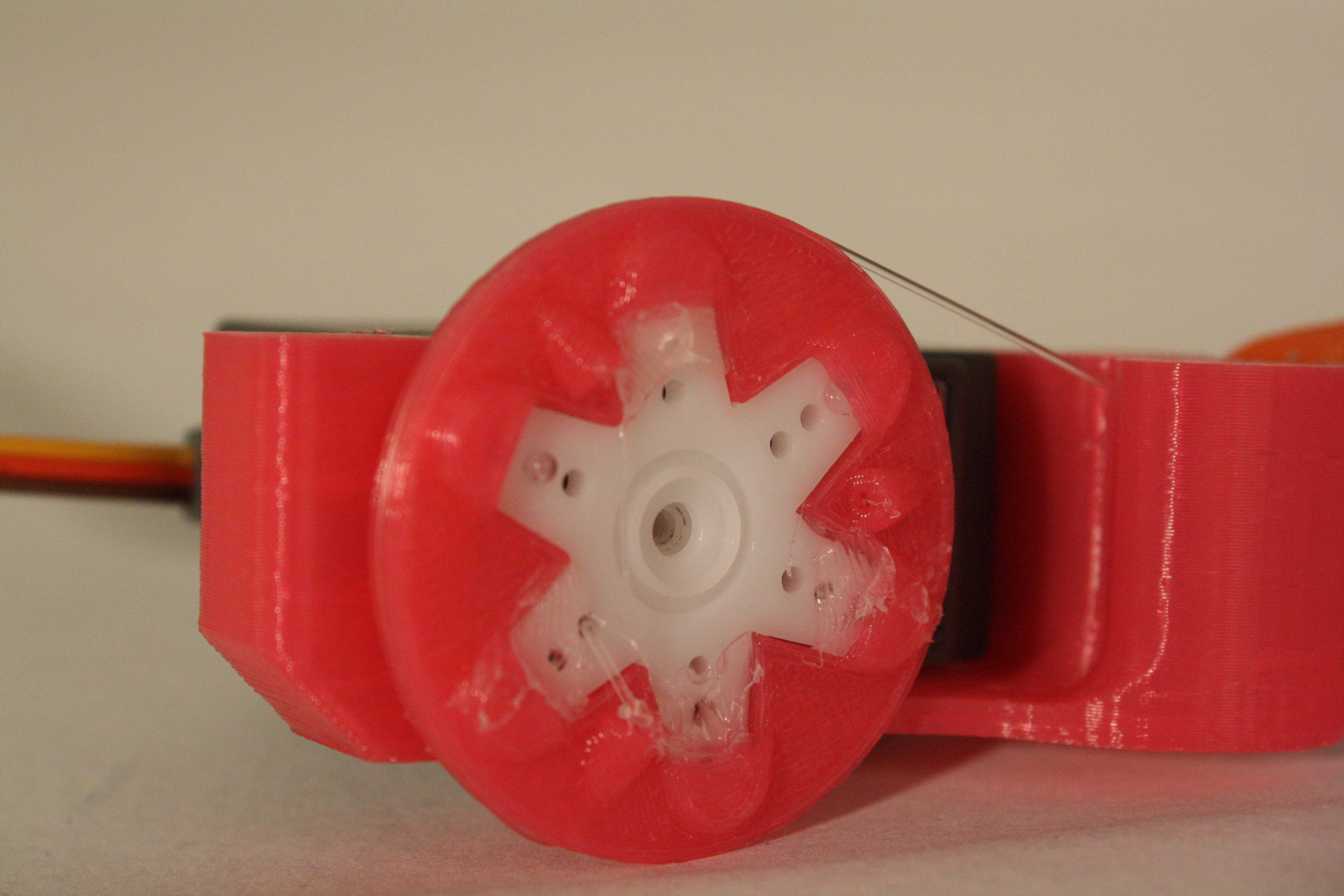
Because the finger has three different bushings, this is by no means a material test. This graphs describes the behavior of whole finger as one functional sample. Around 100 Newtons (~22.5 pounds), the finger transitions from elastic to plastic deformation as the the joints are noticeably being displaced. At Just over 155 N (~35 lbs), the knuckle bushing actually slipped from its socket and eventually broke (after ~67mm of total extension). The striking thing to notice, though, is how far the finger pulls apart before deforming permanently. Polyurethane is truly an amazing material, if you ask me. In any case, this is plenty of strength for us, especially when we add four fingers together and have fishing wire actively keeping the joint from pulling apart. With that, our finger design was complete…well, it should have been.

Notice how far the bushings stretch before one slips.

Notice how far the bushings stretch!

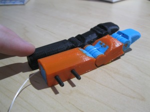
When the first prototype of the claw (covered in the next blog entry) was finally assembled and the fingers plugged in, everything worked well so long as you were willing to pull as hard as possible to get the fingers to flex. Point being, the fingers have way too much friction because of their fully enclosed (and partially polyurethane) guide channels.

The next iteration of the finger plans to sport significantly less restrictive pulleys to reduce friction, which will hopefully be the last improvement before the fingers work like a charm.

Thanks for tuning in, and come back soon to see the first iteration of the claw!

-Myles

Finger Iteration 7.6 (+ Testing Rig)

Hey all, time for more 3D printing experimentation with Myles,

As we wind toward crunch-time, we’re also finalizing the mechanical design of the finger. There have been so many tweaks that I haven’t bothered making a post for each one. Instead, I feel it will be easier to digest a summary of the progress up to now.

Looking Back: V5.5

IMG_7628

This iteration was a huge success in how it printed and how it flexed. The polyurethane bushing, using a modified star cross-section, was very easy to bend. However, this also represented my first attempt to cover the finger in a polyurethane skin, and I realized just how hard 85A polyurethane is. In that respect, the finger didn’t do very well, so I immediately moved on to ways of making the already flexible filament even more soft.

Experimental Axes: V7

IMG_7634

After trying a couple of different shapes that were all too stiff, I came to the almost-successful V7. This much larger finger had polyurethane around both side and the top, making it pretty soft all around. It had complex contours to mimic a real finger belly shape. It even featured a custom hex infill pattern to drastically lower the density. However, it also came with a whole host of problems:

  • Because of the complex shape, it had to be printed on its side. This meant that the torsion bushings had to be printed erect, rather than sideways. Unfortunately, printing upright cylinders is a big faux-pas in 3D printing because the grain of the cylinder in this orientation causes dozens of tiny stress concentrations that totally wreck the cylinder’s shear strength. The graphic below from think3dprint3d.com shows what I refer to.
    Why cylinders should not be 3D printed upright.

    Why cylinders should not be 3D printed upright.

    And of course, the bushings immediately sheared when I tried to bend the finger.

  • Because the skin now covered the joints, I could not string the fishing wire through the palmar side of the finger (d’oh!).
  • I intentionally put dips into the polyurethane skin so that it would crease and fold like a real finger. This came back to bite me because the skin folded so well that it jammed into the joint itself, preventing it from fully closing.
  • Despite the fancy hex infill polyurethane still provided too much resistance. It needed to be softer.

The Newcomer: V7.6

IMG_7645IMG_7648

The latest iteration, while it looks very different from V7, is actually from the same ABS body. I simply stripped most of the polyurethane away and replaced it with a much smaller, more sparse padding over each joint. This finally made the polyurethane soft enough to be viable as a finger, even though I wish I could have covered up the joints (as a stylistic choice). Sporting simple hexagonal rods as torsion bushings, this finger is almost ready to be called the final prototype. Though I could over-work the finger happily for another whole semester, I only have time to make these final changes:

  • The print, as you can tell, is very messy. I will try one more time to support the giant overhangs in the padding so that they print a little cleaner.
  • The PIP joint (closer to the palm) still can slip beyond straight and actually bend backward. I will simply have to add a more robust stopper in the design.
  • I got rid of the dorsal string (to pull the finger back to straight) and hoped that the rebound inherent in the torsion bushing would be enough to open the hand. It almost is, but for safety I think I’ll add a channel for the dorsal string again.
  • I got used to how well Ninjaflex filament sticks to a build plate at 50C with blue painter’s tape. When only ABS is touching the build plate, I’ll need a raft to keep it from peeling.

Integration

IMG_7641

With the finger at a close-enough-to-done prototype and the electrical side up and running, it’s time in the project to interface the finger with a servo. While the final interface/housing will undoubtedly look different, I whipped up a minimalist setup to give the electrical team something to experiment with and to guide my final design. It consists of two simple parts:

The Slot

IMG_7674The slot (bottom-right of picture) gives the finger a simple “plug-and-play” style so that I can make the finger a distinct unit for printing and the housing only has to have the appropriate tab shapes at the end to be compatible.

The Pulley

IMG_7658

The pulley is a simple piece that turns the six-legged servo horn included with the servo into a pulley for the fishing line. It sports three insertion points for the string so that it can be anchored to the pulley. The reason for using a pulley instead of simply tying the string to a servo horn is to ensure proportional angle-distance control throughout the rotation. It may not be the most robust, but for simplicity it is currently just hot glued to the servo horn.


And with that, this mechanical update is concluded. Updated Ninjaflex post coming soon, and a lot more development will be coming very fast in the future.

IMG_7651

Thanks for tuning in!

-Myles

Index Finger V5.5

The actual finger model didn’t change much this week, but the small amount that did change taught me quite a lot.

REV55-PRINT

Index V5.5 mid-print, showing the torsion bushings printing inside the joints.

Modeling Flaws

I certainly expected this, but the model leaves a lot to be desired. Currently, the polyurethane skin is simply dovetailed onto the V5 body. Thus the skin fits very poorly and, for the most part, is too thin to be soft and malleable like a real finger. The next iteration will have to be re-CADed to account for thinner ABS phalanges.

V55-COMPARE

Polyurethane Adhesion to the Build Plate

From now on, I’ll be using “Polyurethane” and “Ninjaflex” interchangeably because Ninjaflex filament is just a propriety polyurethane filament. The skin in the model was “draped” over the sides such that narrow strips of polyurethane touched the build plate. I didn’t expect, however, just how much the polyurethane would stick to the build plate. It was nearly impossible to pry the finger off the build plate, and doing so took a huge chunk of Kapton tape with it. 110 C is simply so hot that the polyurethane melts completely onto it and sticks hard. From now on, I’ll have to make sure that either polyurethane or ABS is touching the build plate, not both.

Relative Joint Stiffness

Another problem that I came across in both this print (V5.5) and the last (V5) is the difference in stiffness in the two joints. Currently, the torsion bushings in the Distal InterPhalangeal (DIP) and Proximal InterPhalangeal (PIP) joints are the same. However, their ranges of motion are quite different (~120 degrees for the PIP, ~90 degrees for the PIP). This throws off the dynamics of the finger as it flexes because the joints bend inaccurately relative to each other.

Also, when the finger first comes off the build plate and is flexed, the first flex is significantly harder than all subsequent flexes. This may simply have to do with material shifting and loosening, but I worry that it is the polyurethane tearing. I will have to slice V5 open to verify this. In either case, the PIP joint, having a wider range of motion, gets “loosened” more, and so becomes even less resilient than the DIP. In future iterations, I will have to look deeper into the dynamics of finger flexion to see if I can get my prosthetic finger to match.

The V5.5 finger is much easier to flex due to smaller torsion bushings.

The V5.5 finger is much easier to flex due to smaller torsion bushings.

Next Steps

It may take a little more printing, but there are two important tests I want to run on the current design:

  • Fatigue: I plan to hook up the finger to a simple rig that will pull the finger back and forth to simulate flexion/extension over a long period of time. This will let me evaluate how the torsion bushings wear over time.
  • Shear: While the hinge joints are pretty sturdy in bending and compression, their tensile strength is solely dependent on the shear strength of the torsion bushings, which are pretty small. I’ll throw the current finger model in our Instron machine and see when it breaks. I’ll compare that to whatever data I can find online about real fingers or current prostheses and see how they compare.

That’s all for this week’s mechanical update. Thanks for tuning in, and as always, let us know if you have any feedback!

-Myles

Surprise! Ninjaflex Improvements

V5-PRINTBED

Woo! A bout of unexpected success yesterday afternoon from the 3D printing side: I managed to synthesize a few resources into new printer settings and got the Ninjaflex to print “consistently!” You can find the Makerware custom profile at the bottom of the post.

V5-PURGEIt’s not perfect, as you can tell from the relative cleanliness of the purge walls. The orange Ninjaflex polyurethane had trouble extruding in tandem with ABS, especially with how little polyurethane was printing. Interestingly, the problem arises when the polyurethane extruder drags over already-printed ABS, which remelts small amounts of it and clogs the extruder. The new settings compensate simply by disabling filament retraction on the Ninjaflex extruder (which is normally on to keep blobs from forming). The extruder also pushes extra filament out at every tool change to ensure that the clogged ABS gets pushed out.

The other major change is extruder speed. Ninjaflex slips very easily on the extruder gear so it can’t be forced to print very fast. Thus I had to bump down the print speed on that extruder to a sluggish 15 mm/s for all operations. Thankfully, the ABS still prints at full speed.

For next time, it’s back to SolidWorks to work on finger version 5.5!

Ideas for 5.5:

  • I still have to add ~20 degrees of motion before the hard stops to get a realistic range of finger flexion.
  • I’m definitely going to add a Ninjaflex skin to this finger. I want to see how it affects the gripping strength of the finger as well as how it prints with more flexible filament involvement.
  • The fingers joints are still a little too stiff. It turns out I need very little bushing material to get a good amount of rebound. Obviously I can shrink the bushings to get a smaller torsional stiffness, but that would also compromise its sheer strength. Instead, I think I’ll take advantage of the geometric freedom of 3D printing and try to make the bridle joint bear some of the load.

Until next time,

-Myles

Makerware Custom Profile for Printing Ninjaflex and ABS on the Replicator 2X:

Continue reading

Finger Rev 5: More Ninjaflex Problems

A new semester is here, and so progress on the 3D printed finger resumes. Unfortunately, the problem from the end of last semester remains: Ninjaflex is hard to print with; it clogs constantly and it’s so soft that the extruder gear has a hard time pulling the filament through. No matter how much I floss the barrel and tighten the plunger set screw, it just doesn’t want to extrude. In the coming week, I’ll have to dive back into the depths of custom Makerware settings, but this past week yielded a few good bits of progress.

Firstly, the 5th iteration of the index finger design is now in Solidworks. This iteration boasts a more biomimetic shape and an accurate range of motion to my own left index finger. This version also has channels for string through both the dorsal and palmar sides, theoretically allowing for tension control. Finally, I simplified the torsion bushing to mimic the socket of a Torx-head screw, hopefully making the hand calculations-to-come a bit easier. The result looks something like this:


REV5-SKETCH-2


RENDER1


On the fabrication side, I did manage to prove one thing: the flexible filament will print, but not without a fight (and some setting adjustments). I printed a model out of only flexible filament and it worked, though not ideally.

flex-beforeflex-after

This squishy little Typhlosion model served as my test piece. As you can see, it really does squish and rebound quite well.

flexitar

However, you can also see that it didn’t print perfectly. Some spots got a little sparse on Typhlosion and the purge wall definitely had trouble keeping up in the middle of the print. On the bright side, this tells me that I can still adjust my flow rate and/or print speed and that problem should fix itself.

However, it also proves that the Ninjaflex can print itself, and yet it clogs up very quickly when printing alongside ABS. This implies perhaps that my retraction settings are still off, and that will be tricky to figure out. Even worse, this may imply that the ABS that gets clogged in the tip of the Ninjaflex-extruding head is enough to completely block the Ninjaflex. This could happen because the Ninjaflex is so soft and slips so easily over the extruder gear that it may not be able to generate the necessary force to push out the clogged ABS. This is the main problem I’ll be tackling next week.

Thanks for keeping up with our journey. That’s all for this week’s mechanical update.

-Myles

P.S. If you have any suggestions about what I should be doing or how I should be debugging this issue, let me know at myles.cooper@students.olin.edu. Feedback is greatly appreciated.

Mechanical Update: Flexible Filament

Phew!

Sorry it’s been so long everybody. I admittedly have not been able to spend as much time on the project as I would like to, but I finally have an update: flexible filament is working. We recently bought half-a-kilogram of NinjaFlex filament so we can experiment in the realm of squishy things. Right off the bat, I’d like to point out that I’m not necessarily going in the “best” or “most efficient” directions right now; I’m exploring. The reason is that I recognize that I am new to the world of prostheses and that people much more experienced than I have spent much more time on developing robotic and 3D printed hands. I know that polyurethane molding can be easier that printing flexible filament. I know that under-actuated fingers don’t need to be printed the way I’m doing, but that’s why I’m doing it. Other people working on these types of projects are working toward viable, potentially marketable deliverables. As a student, I am fortunate enough to have the room and flexibility to do things simply because they haven’t been done. I believe there is some value in trying things simply because you can if the opportunity presents itself. Otherwise we become too clouded by the “right way” to do things, and creative thinking becomes much harder to manage. I’ll get off my soap box now, though, and step onto another one.

Printing Flexible Filament

…is hard. The Makerbot Replicator 2X’s that I’ve been working with, while great hobby printers, are not meant to print much more than ABS and dissolvable filaments. After too many hours of Google searches and setting adjustments, though, I finally got a test block of half-ABS, half-NinjaFlex to come out cleanly.

The ABS (white) and NinjaFlex (orange) test block

The ABS (white) and NinjaFlex (orange) test block

As you can see, the NinjaFlex is quite flexible indeed (about 85A hardness, according to the manufacturer, which is right around the hardness of an average polyurethane longboard wheel). My hope is that this flexibility allows me to use the flexible filament as a torsion bushing for the finger, removing the need for dowel pins. As much as I love dowel pins, they caused a whole lot of friction and installment problems that I didn’t care for.

What This Means

With this new manufacturing technique, I get the unique ability to have these bushings fully encased in the finger. One of the things I’ve always loved about dual extrusion 3D printing is that it allows for things to be locked together simply by printing them locked together. This opens door for fingers that actuate right off the build plate, and perhaps even prosthetic fingers with hard “bone” centers and squishy “skins,” printed all in one piece.

Though the settings aren’t yet perfect, I’m on the trail of having full control over 3D printed hybrid flexible/rigid assemblies. If you have any suggestions for how I should use this method, shoot me an e-mail at myles.cooper@students.olin.edu.

Thank you all for tuning in, and I look forward to sharing more progress with you soon!

-Myles